Last updated: 9/13/00
Popular inexpensive brake improvements for the 90+ 300ZX include Stainless Steel brake lines, racing brake fluid like Motul, and high performance brake pads and/or rotors. Due to a lack of prefabricated brake ducting available for this car I set out to create my own set up. With the help of some friends, we developed the aluminum bracket and routing method illustrated here.
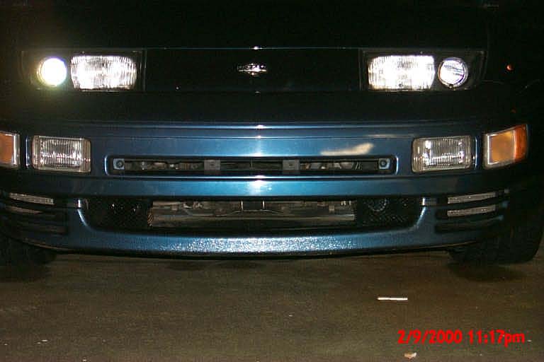
This installation was done on my '92 twin turbo with stock calipers and rotors.
Timing:
Any time the front wheels are off.
Special Tools:
1. tin snips
2. grinding wheel
Special Parts:
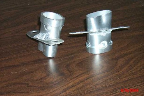
1. caliper mounted duct bracket (A) (build yourself or order
from me)
2. ~8' of 2" brake duct hose
3. 2 brake duct funnels
4. at least 4 hose clamps
5. zip-ties (preferably black)
6. 4 Earl's SS brake line fittings #640303 (or 2 #640303 and 2 each
of #600103 & #592032, see text)
7. 2 10" pieces SS brake line
Installation (click on images for large versions):
1. Break loose all lug nuts for wheels involved. Get the car in the air, enough to get the wheels off the ground. Make sure all jack stands are properly placed, & all safety measures are taken. Remove lug nuts & wheels for access to calipers.
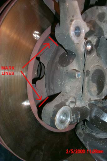
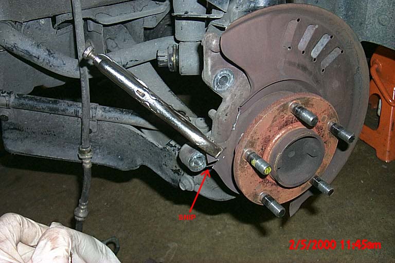
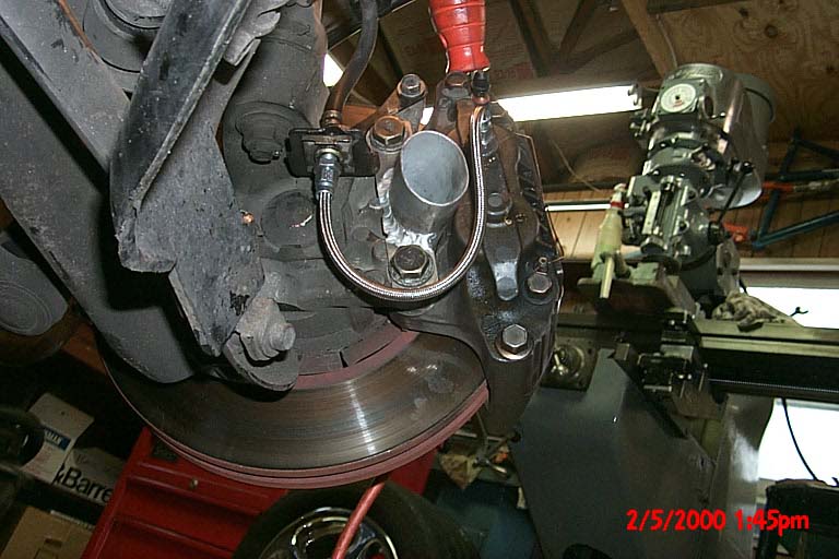
2. Remove calipers and mark or scribe lines on the inner shield where shown (1). This will allow the air from the duct bracket to enter the rotor cavity (2).
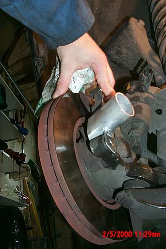
3. Remove rotor and use tin snips to cut the inner shield where you made the marks. Using vice grips or similar pliers, bend the shield repeatedly until you break off the two pieces (3).
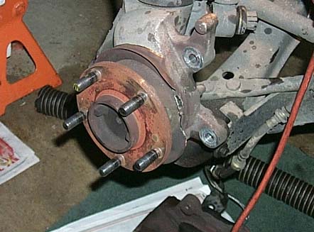
4. We chose to cut off the inner rock shield to allow better air circulation around the rotor, and to allow us to do the next step. We found it easiest to do using a die grinder (4).
5. We then used tin snips to cut the inner shield about every inch, radially (5), then flared it out to make a "seal" to the inner diameter of the rotor (6). This was done to force the ducted in air to exit the rotors radially. NOTE: in the stock configuration, air is sucked into the rotors through this opening, and this step prevents this from happening. Without the ducting in place, the brakes could overheat rapidly (during brake intensive driving).
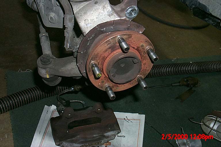
6. Next we installed the new stainless steel brake line to replace the stock solid line which exits the caliper and cuts straight across the opening that we mount our bracket over. We used Earl's fittings #640303 & 10" of Earl's SS brake line. Follow the manufacturer's recommendation for installation. If you use the non-swivel fittings on both ends, getting the line installed with out being all twisted up will be a little tricky, but we did it! Alternatively, it was suggested to us by Scott at Frey Racing to use the #640303 at one end and the 2 piece swivel fitting #600103 & #592032 at the other end, but we haven't tried it. Mount the caliper and the new duct bracket with the caliper bolts and torque to 72-87 ft-lb (7)(8).
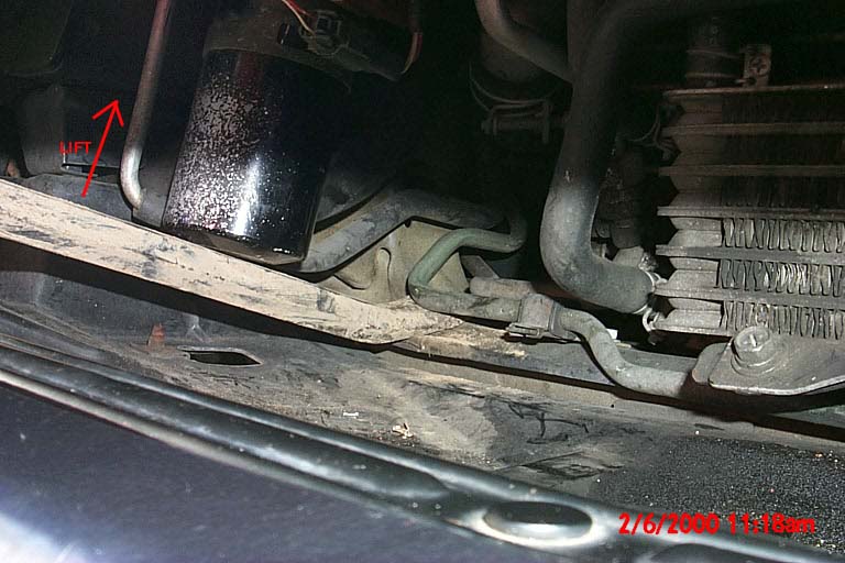
7. Now, to route the duct hose on the passenger's side, the A/C dryer unit will have to be raised. Loosen the bolt that secures its clamp band (9), and pry the unit up with something suitable (10). Tighten the bolt while you hold the unit up. Don't damage anything!
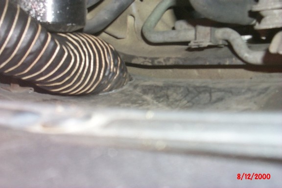
8. Cut holes in the lower plastic pan for the hose, making use of the two existing holes. I used a soldering gun to "cut" them, as I didn't have a better cutting tool...(11)(12)
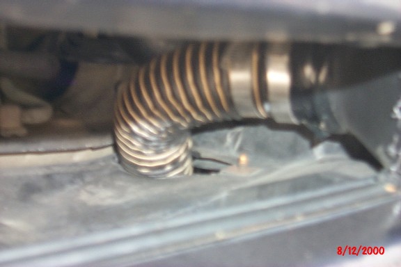
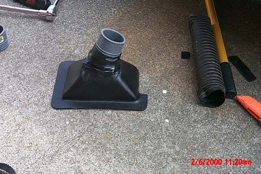
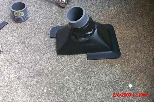
9. Cut part of the flanges off the air funnels to fit into the corners of the car's opening. To use the 2" duct hose (also see options at bottom of page), the funnels have to be shrunk down to fit around a coupler. I used a heat gun and softened the plastic while stretching it and made it conform to the 2" PVC hose coupler. On the passenger's side, I also had to give it an angle so that the hose would go under the A/C dryer (13)(14)(15).
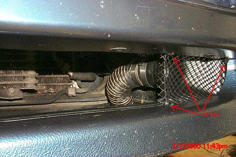
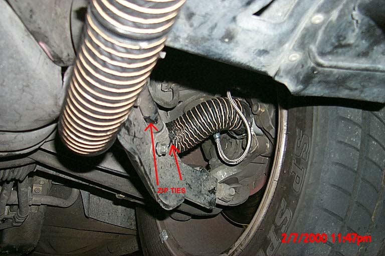
10. Drill 3 small holes through each funnel and the car to thread the zip-ties through. I used a piece of black plastic rain gutter screen over the front of each funnel to keep large debris out. It's held in place by the zip-ties too (16).
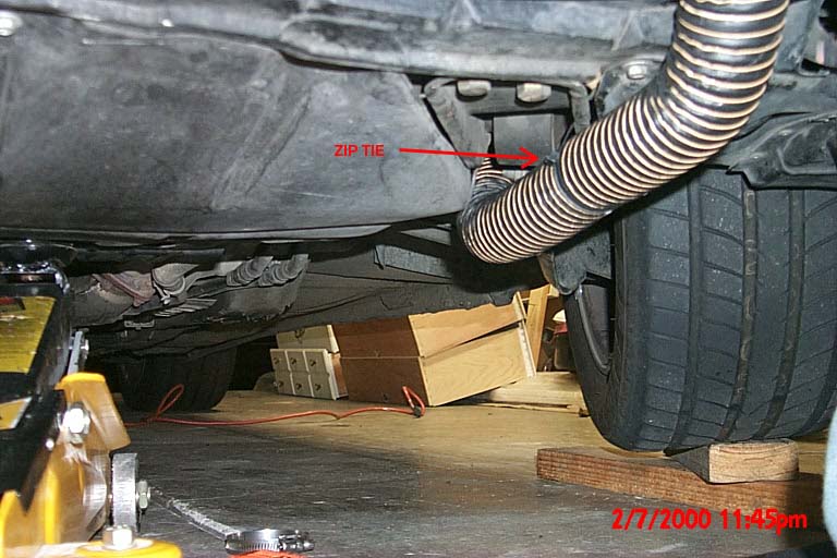
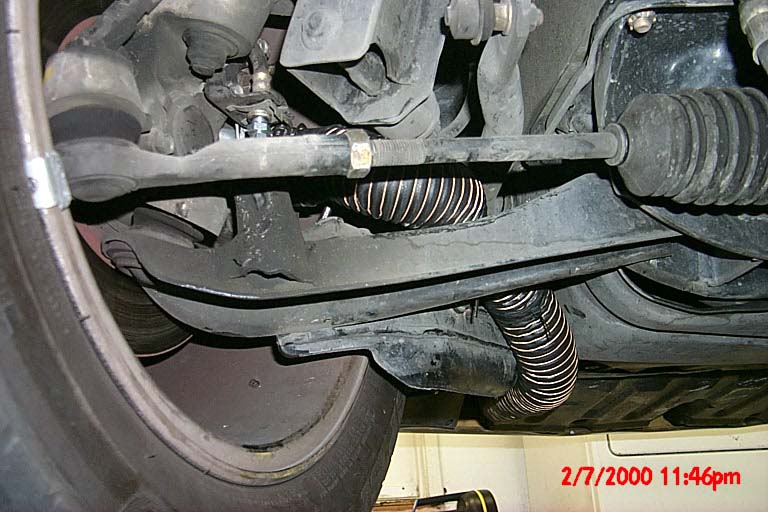
11. Connect the hose with hose clamps and run it through the openings in the lower pan. Run it back along the inboard side of the tension rod, securing it with zip-ties along the way (17). Route the hose in between the tension rod and the anti-sway bar up to the caliper bracket. Be sure to use enough hose that when the wheel is turned out, the hose isn't too tight, but not so much that when the wheel is turned in it gets bound between components. The bracket should position the hose (due to its angle) so that it slips between the tension rod, sway bar, lower control arm, and shock bottom when turned in. Use hose clamps to secure the hose to the brackets (18)(19). (In #18 the wheel is turned in and the picture is taken from the back, and in #19 the wheel is turned out with the picture taken from the front)
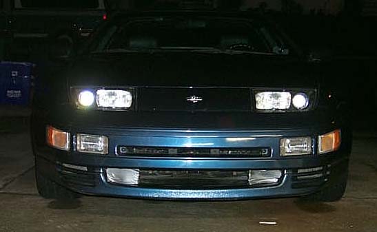
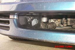
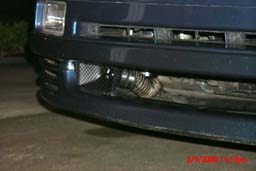
12. When finished, the funnels are difficult to see for the unfamiliar (20), without getting down low (21) or using a flash (22).
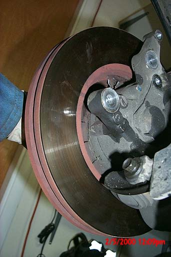
13. In order to bed new brake pads, I found it helpful to put duct tape across the plastic mesh to block the air. I wanted to get the pads and rotors to get nice and hot! (23)
14. Torque lug nuts to 78ft-lbs using a crisscross (skip 1) pattern. Do this with a proper torque wrench.
For 2 optional installation methods, click here.
Layout and tire removal & installation text plagiarized from: Twin Turbo Zs of Dallas Thanks guys!
1. 2.
2.
3.
4.
5.
6.
7.
8.
9.
10.
11. 12.
12.
13.
14.
15.
16.
17.
18.
19.
20.
21.
22.
23.